This section contains graphics materials accessible through buttons on the navigation bar above. Some of the items include demos of computer graphic methods and papers disclosing novel solutions to graphic problems. Source code is also included for some applications.
The contents of the navigation subsections are:
All of the graphics in this section are 2D — there are no 3D, much less 4D applications, as might be suggested by the animation above. I may include a section on 3D graphics at a later time, but for now this is it. Unfortunately, the code which implements the algorithms is not portable, because it was written with Intel '86 assembler language and Borland C++ Builder using modified bitmaps.
Screen shot of line demo program.
The common objective in creating a viable line drawing algorithm is to plot points of a grid-restricted line which most closely match an ideal continuous line joining the end points. In other words, each plotted point must be the closest grid point to the desired line. There are, of course, many ways to solve this approximation problem. Each has its own strengths and weaknesses, and a major concern in devising an algorithm is to eliminate performance bottlenecks. Bottlenecks in line drawing primitives come in several flavors. Processor intensive floating point operations, type conversions, divides, complex integer operations (shifts, rotates), compare and branch instructions, etc.
A number of efficient solutions which avoid the most serious bottlenecks have been proposed by Bresenham and others. These algorithms use incremental techniques which, for the most part, involve only simple integer operations. Some, like the midpoint algorithm, are derived directly from the nearest point requirement. Typically, algorithms are defined for a restricted range of line slopes and separately coded for each octant or require signed integers which are precomputed for the particular octant under consideration . See any text on computer graphics for explanations, derivations and examples.
Details of the proposed new algorithm are documented in this pdf file. Unlike other line draw algorithms, this method is derived from sample rate conversion concepts, in particular decimation. Mapping the problem to a signal processing domain leads to efficiency improvements which are not obvious in the original line drawing context.
The new algorithm avoids common performance bottlenecks by using a special, normalized integer control variable to perform updates within the inner loop. Recall that the usual strategy for drawing lines in the first octant is to increment the 'x' position at every iteration of the pixel drawing loop, and to increment the 'y' position periodically as determined by some update strategy. Our strategy is to begin with the quantity dy/dx, representing the slope of the line, which ranges from 0 to 1 in the first octant. We produce a scaled version of dy which ranges from 0 to 65535 or 0 to 4294967295 depending on whether 16 bit integers or 32 bit integers are specified. This new unsigned quantity, incr, is effectively the fractional part of a fixed point number having a 16 or 32 bit fractional part. For the 16 bit integer case, incr is calculated from the equation: dy/dx = incr/65536.
Thus, assuming 16 bit integers, if dy/dx=0.5 then incr = 0x8000. If dy/dx = 6/7 then incr = 0xDB6D. These values are found by performing an unsigned integer divide before entering the inner loop. Now, on each iteration of the inner loop, an unsigned integer control variable, cvar, is updated by adding incr to it. Rollover (cvar > 65535) signifies that the 'y' variable needs to be incremented, and since this condition generates a processor carry, we only need to add the carry to 'y' to perform the update. With Intel and AMD processors, the adc (add with carry) instruction with an immediate value of zero does the job. If a decrement is required, sbb (subtract with borrow) would be used.
The inner loop for the first octant looks like this in pseudo-code:
plot(x,y)
increment x
add incr to cvar
add 0 with carry from previous operation to y
loop
In superscalar processors, increments and adds are fully pipelined -- unlike the complex operations such as divide or multibit shift. No explicit decision points are required within the loop because the decision is handled implicitly by carry management. Other than the loop control, there are no compares or branches. No divides, multiplies or shifts are required in the inner loop.
Note that the loop control variable and the 'x' variable both step in unit increments at each iteration. This suggests that it may be advantageous to combine the loop variable and the 'x' value to reduce the number of increments per loop. There are a number of ways to do this, but observe that the extent of any performance improvement is processor dependent. The fourth step in the above algorithm can be eliminated by a method described in the paper.
As with other line algorithms, there are several ways to adapt the above algorithm for use in any octant. Interchanging the roles of 'x' or 'y' maps the basic algorithm from octant I to octant II. Changing the polarity (sign) of 'x' and/or 'y' maps to other octants. Some of the mappings can be most easily done without performance penalties by changing increments to decrements and adds to subtracts. The management of the control variable is the same in each case.
For a comprehensive plotting strategy, the basic algorithm can be implemented 8 times, once for each octant, and a decision tree traversed to identify the correct octant for a particular line, Alternatively, a set of signed loop variables can be generated and the basic algorithm invoked with signed update quantities. Both methods have been used successfully with other line drawing algorithms and can be applied to this one as well.
This algorithm has been implemented in assembler language for an Intel Pentium and tested for correctness (plotting the correct pixels). It was found that all the required variables can be held in processor registers, so no memory accesses are required except for the pixel plot itself. An application using this algorithm is available here.
A more detailed exposition describing the method can be downloaded for additional details.
This paper describes a method for drawing antialiased lines and curves with improved diagonal steps and color blending. It has the efficiency of Wu's algorithm, but provides smoother curves with more uniform color density.
Displayed Curve with Noticeable "Jaggies"
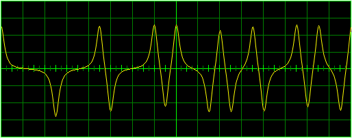
Antialiased Curve Using Wu's Algorithm
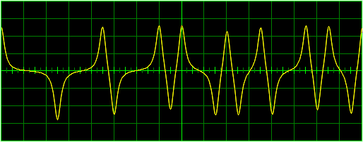
Antialising with Improved Diagonal Steps and Color Blending
The screen shots above provide a direct comparison of the curve appearance when different methods are used. The lower plot is an example of the line quality supported by the techniques described in the paper.

Screen shot of Windows Arc Demo
Although students of graphics algorithms are well acquainted with the incremental algorithms of Bresenham and the midpoint strategies devised by others, these algorithms only directly address lines and circles (or ellipses). There is very little published literature dealing with the problem of applying the same strategies to arcs. A new method, described in the paper available here, uses the algebraic properties of oriented lines to distinguish pixels along the circle which are on the arc or outside it. Source code for a simple DOS demo file in the C language is also provided. The Windows Demo shown above was built using the same C code.
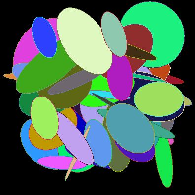
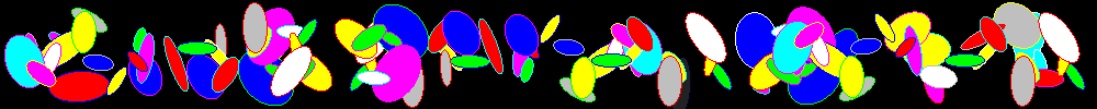
Screen shot of ellipse demo.
Efficient graphics primitives supporting ellipses at arbitrary orientations and aspect ratios are relatively rare. Unfortunately, the published algorithms typically fail to plot the correct pixels for ellipses with large aspect ratios. The problem occurs at the corners where the derivative of the curve may change drastically over a sub-pixel distance. A paper which describes a new method which solves this problem is available, and a Windows application demonstrating it can be downloaded here. Note that the screen shot above contains ellipses that are highly elongated -- a serious problem for previously published algorithms. Here is a link to an updated version.
Here is a paper which describes an efficient and versatile flood fill method which supports advanced fill options. The paper discloses a method which only visits each processed pixel once, and can therefore support the transfer of arbitrary pixels into the filled regions. Algorithms are presented in pseudo-code and a complete implementation of the lowest level scan and fill routines in Intel assembler language are provided. The paragraphs below show some of the capabilities of the method.
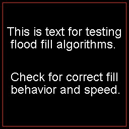
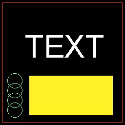
Basic starting screen


Standard Flood Fill
Flood Fill with Flood UnderGiven the starting screen shown above, and filling the black background with blue, how does your flood fill algorithm perform? Chances are, it produces a screen like the standard flood fill image above. This is the result of invoking a conventional surface fill algorithm such as the one in the Windows API. The third image above is the result of invoking a flood fill with flood under capability. Flood under is just one of the new features of a flood fill library I have created to manage extended special fill requirements. This particular feature is most useful when an image has been partially covered with text and it is necessary to fill the background including the closed regions within the text characters. The flood under feature allows the caller to specify one color to ignore during the fill. This color is neither filled nor treated as a boundary, so the algorithm will treat any other color (other than the original surface color or the flood under color) as a boundary. The effect is to 'elevate' the text or other graphics object to the foreground and fill underneath it.
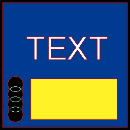
The above images show the effects of invoking flood fill with the reborder option. This option allows the caller to specify a particular color to re-color any border pixel. In this case we have flood filled the black background surface with blue, and re-colored the border pixels with red. This can be useful for forming outlines of text or graphics.
Another available option for filling a surface is to copy pixels from a second bitmap pixel-for-pixel into the region to be filled. The image below fills the region enclosed by the elliptical frame with pixels from a bitmap of the image processing standard picture of "Lena". The flood-under option was also used so that the text appears normal. To create this image, white text was written over a blue background, then a yellow ellipse was drawn over it. Then the fill algorithm was invoked with the fill-from-bitmap and flood-under options for the interior of the region and called again with a gradient fill option for the external region. Gradient fills are available to fill with colors from a table indexed by the 'y' coordinate (as in this example) or the 'x' coordinate.
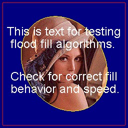
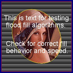
Fill from Bitmap with Flood-Under Same Image with Gradient Fill Added
<\div> <\body> <\html>