
On these pages you will find notes on filters, accurate coefficients for specific filters, and software for solving filter problems. See Design Notes on the Circuit Analysis page for additional information.
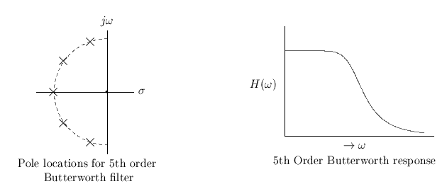
If you're a little hazy about how the pole plot shown in the above left figure leads to the response curve shown on the above right, click on the Refresh or Reload button on your browser's toolbar. The animation below zooms in on the filter response surface in the left half of the complex plane to show the magnitude response along the frequency (imaginary, jw) axis. The 'zoom in' simply consists of scaling the vertical dimension (magnitude), so the complex plane scales (s, jw) remain fixed.
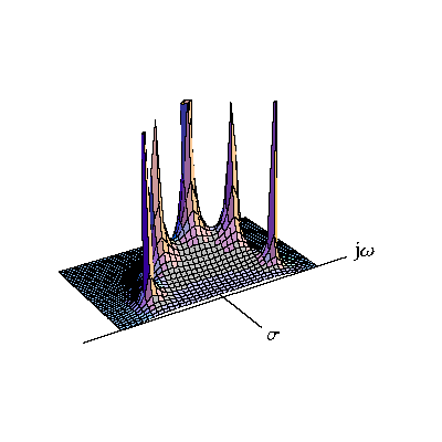
Response of 5th Order Butterworth Filter over the Left-Half Complex Plane.
Note the open area under the lower right of the figure which represents the filter response and which illustrates the conventional frequency attenuation curve as the animation progresses.
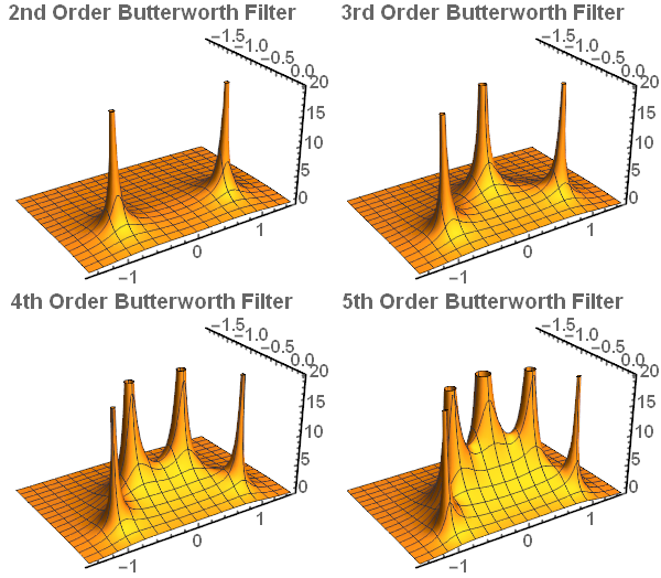
Magnitude in Left-Half Complex Plane for Butterworth Filters of 2nd Through 5th Orders
This paper contains transfer functions, equations for amplitude and phase response, equations for group delay for all Butterworth filters up to order 5. Extended tables of Butterworth polynomials, poles, and circuit elements are provided in a separate paper, for filter orders up to 10.
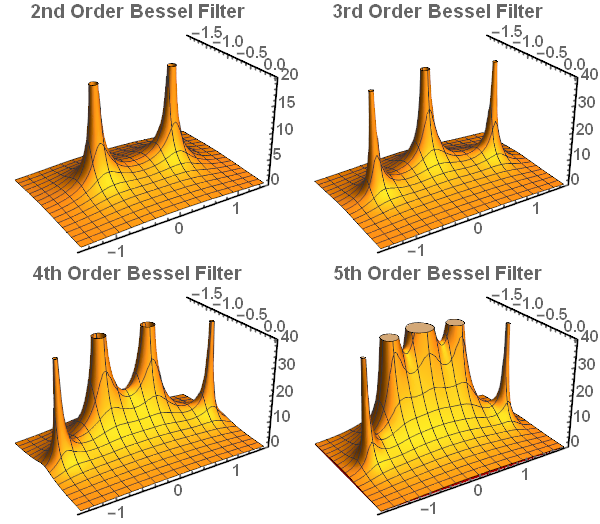
Magnitude in Left-Half Complex Plane for Bessel Filters of 2nd Through 5th Orders
Here are the transfer functions, equations for amplitude and phase response, equations for group delay, and normalization constants for all Bessel filters up to order 6. Extended tables of Bessel polynomials, poles, and circuit elements are provided in a separate paper for filter orders up to 10. Parameters are given for delay normalized and frequency normalized filters.
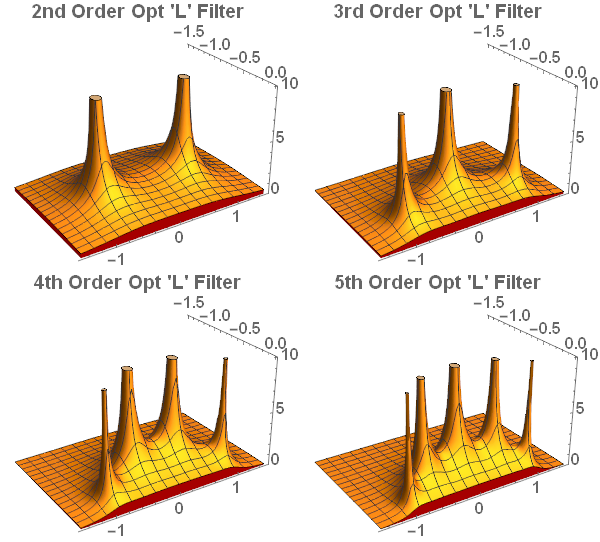
So called "Optimum Filters", presented by Papoulis in 1958, exhibit maximum rolloff for a monotonic filter of given order. His original paper treated filters of odd order only, and it wasn't until his follow-up paper in 1959 that he completed the presentation for even orders. Tables of Optimum polynomials, poles and circuit elements are provided in this paper for filter orders up to 10. To my knowledge this information has not been published elsewhere. A separate paper describing the algorithms used to compute the filter element values and an example can be found here.
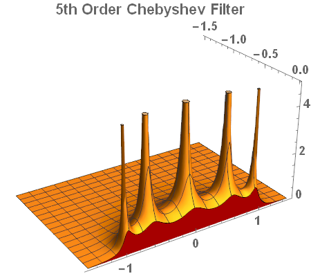
Although Chebyshev Low Pass Type I Filters are all-pole, they permit the designer to specify magnitude ripple in the pass-band. The specification is managed by a user chosen parameter. Hence, such filters, although commonly used, are better specified by a computer program than a list of pre-computed values. The figure above illustrates a typical magnitude response in the complex left-half plane. However, no tables or similar documents are provided for general Chebyshev Type I filters at this time. If I can find a clever way to compact useful design information or elect to include a software program that may change.