
One of the most challenging problems in circuit theory is that of finding the impulse response of a network. This problem is most easily solved by taking the inverse Laplace transform of the transfer function of the network. There are several methods for taking inverse Laplace transforms of certain rational functions, e.g. the ratio of two polynomials in the complex variable 's'. Fortunately, most network functions, including lumped parameter filters, fit into this category. These are networks which can be descrbed in terms of ordinary differential equations.
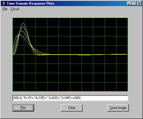
Screen Shot of Impulse/Step Response Demo
For networks involving strip lines, transmission lines, or other distributed parameter configurations, the solutions generally involve partial differential equations. For these networks the transfer function may not be the ratio of polynomials. Prof. Jiri Vlach, in his text "Computer Methods for Circuit Analysis and Design", presents a general method for finding the inverse Laplace transform of network functions which are not restricted to ratios of polynomials. The method is elegant -- and fast. C source code for it, ported from the original FORTRAN, is available here. A somewhat more advanced method which has better performance over long time intervals is also available. It produces the time domain response of any network which can be described by the ratio of polynomials. A Windows application demonstrating the more general method is here.
The text "Engineering and Scientific Computations in Pascal, " by Lawrence P. Huelsman includes a complete set of Pascal modules for circuit analysis. Here is a port of the complete software package into C++, including all routines except the Pascal module for printing plots on a text printer. This package supports the design of complex networks of resistors, capacitors and inductors, along with sources. It may be very difficult to use the package without access to the author's text, but several test programs are included.
If a preferred method for solving networks involves partial fraction expansion of the ratio of two polynomials in 's', a root finder will be required. The Jenkins-Traub method is very robust and has earned a reputation as one of the best in the scientific community. Bairstow's method is well suited to solving the kinds of polynomials common to electronic and mechanical engineering problems, because it can find all real or complex roots without using complex math. It operates on any polynomial with real coefficients.
An original method which offers improved support for polynomials with multiple roots is detailed elsewhere on this website.
Infinite Ladder Network
This paper contains an analysis of several infinite ladder configurations, including the one shown above. Techniques are presented for finding the impedance at the input terminals for each type.
This section contains links to a number of short notes solving problems in circuit analysis and synthesis. The circuits selected represent a variety of commonly used configurations and illustrate typical design techniques.
Bridged 'T' Notch Filter
In this note, you will find a short derivation and solution of the equations for the circuit shown in the above schematic. Simple tips quickly lead to the relations among the components required for a null to exist across the load, RL, and for the determination of the required Rv.
RC Phase Shift Oscillator
A simple RC phase lag network can serve as the basis for an oscillator. Three cascaded RC sections will create a 180 degree phase shift at some frequency. The above circuit is analyzed here to determine the relationship of the components to the oscillating frequency and the minimum gain required for the amplifier.
RC Twin 'T' Notch Filter
Twin 'T' notch filters are often used to reject 50/60Hz interference from AC power lines in sensitive audio circuits. Component values for 'standard' designs are readily available, but this note derives the component relations and offers more general conditions for providing a transmission null through RL.
Don't throw out any old PALs or GALs in your parts box. They may still have some value. Here's a programmable generator which can produce clock periods of 9, 10, 11, 12, 13, 14 or 15 cycles under control of 3 input lines. It consists of a single GAL16v8, which can be found at many hobby-oriented electronics suppliers. Of course, you will also need access to a device programmer.
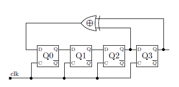
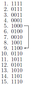
This circuit uses a linear feedback shift register (LFSR) as the basic sequencer. Four 'D' flip-flops are configured to produce a 15 state shift register which forms the basis for the circuit. Assuming the power-on sequence presets the registers, we begin operation with all registers at a high level. The full, 15-state, sequence is shown below. In this table the order, from left to right, is Q0, Q1, Q2 and Q3.
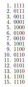
A schematic diagram for this shift register is shown here. The feedback is through the exclusive OR circuit. Logically, the D input to Q0 is: Q2 AND Q3 OR Q2 AND Q3.
Shorter periods can be obtained by detecting one specific state and skipping to a later state using modified feedback logic.
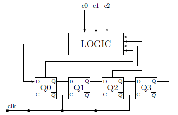
The logic block receives input from each of the registers, which include both Qn and Qn outputs. It also takes input from the control lines, c0, c1 and c2, to select the desired count.
A schematic diagram showing the input/output assignments for the GAL16v8 used in this project is:
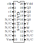
The 'T' output consists of a single pulse which occurs once every count cycle. It is probably the most useful signal from the device, but since the Q outputs are all available they may be used to decode a specific state in the sequence.
A simple strategy for selecting the states to skip with minimal extra logic is to find an appropriate state whose next state would normally introduce a one or zero into Q0 and invert the input for this state. This will work if the new next state skips over n states resulting in a total count of 15-n. If we intend to support counts from 9 to 14 we would have to find appropriate states to support skipping 1 to 6 states. It turns out that the counter which produces 14 counts between occurrences of 'T', is a special case which requires a different method. It will be discussed later.
Let's start with a divide by 9 counter. Note that counts of 8 or less can be done with fewer registers and we are presenting a method using 4 registers.
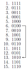
State 6 has two identical entries in Q2 and Q3 so the linear feedback term would be 0. However, if we invert this and place a 1 there, the next state will be state 13. If no other changes in feedback are active the total count will be 9. For this counter we simply detect state Q0Q1Q2Q3 and force the D input of Q0 to 1. On closer examination, we find that all we really need to detect is Q0Q3.
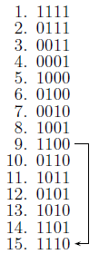
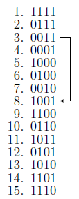
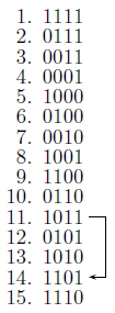
For these counters we need to detect Q0Q1Q2, Q0Q1, Q0Q1Q2 and Q0Q1Q2, respectively. If each term is ANDed with the chosen state of the cn inputs, and each of the resulting terms is ORed with the original linear feedback term, the programmable counter is complete --- almost. There remains the 14 count sequence which cannot be coded with the method previously explained. The only way to skip a single state by modifying the input to Q0 is to invert the feedback 1 in state 15 so that the next state will be state 2.
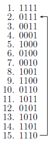
In this case, the count sequence is enclosed by the from and to states, rather than enclosing the skipped states. To force a 0 at the D input of Q0 we need to disable the feedback and all other logic at state 15. Also, the desired sequence skips the initial, preset state and won't begin until the maximal length count has occurred once.
Assigning combinations of the control inputs is arbitrary, but the following table shows the chosen values.
c0c1c2 count
0 0 0 15
1 0 0 9
0 1 0 10
1 1 0 11
0 0 1 12
1 0 1 13
0 1 1 14
1 1 1 15
The combinations not used to select counts below 15 simply default to 15. This assures that no unexpected behavior occurs.
The programming logic for this device using CUPL software to generate the JEDEC file is reproduced below.
/*********** Input *************/
PIN 1 = clk;
PIN 2 = c0;
PIN 3 = c1;
PIN 4 = c2;
/*********** Output ************/
PIN 16 = Q0;
PIN 17 = Q1;
PIN 18 = Q2;
PIN 19 = Q3;
PIN 15 = T;
PIN 14 = W;
/** Declarations and Intermediate Variables **/
cnt9 = c0 & !c1 & !c2 & !Q0 & !Q3;
cnt10= !c0 & c1 & !c2 & Q0 & Q1 & !Q2;
cnt11 = c0 & c1 & !c2 & !Q0 & !Q1;
cnt12 = !c0 & !c1 & c2 & Q0 & !Q1 & !Q2;
cnt13 = c0 & !c1 & c2 & Q0 & !Q1 & Q2;
cnt14 = !c0 & c1 & c2 & Q0 & Q1 & Q2;
/*********** Logic *************/
Q0.d = (Q2 $ Q3) & !W # cnt9 # cnt10 # cnt11 # cnt12 # cnt13;
Q1.d = Q0;
Q2.d = Q1;
Q3.d = Q2;
T = Q0 & Q1 & Q2 & !Q3; /* choose any state which occurs in
all counters as the period clock signal */
W = cnt14;
The all-important header for this file is not shown, as it will vary depending on the specific user details. The output variable 'W' is an example of using an output to provide a signal which is required by the application, but which is unavailable for the desired output due to limitations on the number of fuses in the device. The following symbols are used as logical operators.
$ = XOR
& = AND
# = OR
Note that the counter which produces a period of 11 is well-suited to drive a communications link using a serial protocol which consists of 1 start bit, 8 signal bits and 2 stop bits.